News
Current Location:Home > News


Wear and failure mechanism of brazed diamond tools
Date: 2021/2/1
Source: China Grinding Network - 91 issue of China Grinding magazine
Zhengzhou Abrasives Grinding Research Institute Wang Guangzu Wei Fengwu
Cui Zhongming and Feng Changcai, School of Mechanical and Electrical Engineering, Henan University of Technology
1. Failure mechanism of different brazed diamond abrasives
For single crystal shear experiment, the main measurement is the bonding strength of single crystal/solder after welding, the fruit is the brazing layer broken, the breaking strength of the order is CuSnTi brazing >AgCuCr brazing BBB>CuTi brazing BBB2 C>r brazing; For the mechanical properties of the filler metal itself, the mechanical properties of the filler metal alloy itself (including hardness and shear strength), the order is NiCrBSi brazing family >NiCrP brazing material BBB>SnCr brazing material BBB2 C>i brazing material BBB3 AgCu>razing material BBB4 AgCuTi >ing material. Than results shows that besides CuSnCr filler metals, other solder corresponding to the two kinds of results, combining with the results of the temperature on the compressive strength of diamond, this is because the CuSnCr solder against high temperature, temperature and solder erosion strength of diamond itself down is serious, so the single crystal in smaller when shear force under the action of the fracturing, the corresponding shear strength is also low, from NiCrBSi and NICrP single crystal directly after welding to failure as you can see it.
From the shear results of diamond grits, it can be seen that the shear failure modes of diamond samples prepared by different solders are different with the same shear force arms. The main failure mode of gold carbide brazed by NiCrBSi is breaking and accompanied by macroscopic crushing. The main failure mode of NiCrP brazed diamond is fracture accompanied by macroscopic fracture and the degree of fracture is a little smaller. The main failure mode of Agcuti brazed diamond is crushing slip and tends to be pressed into solder metal. The main failure modes of AgCuCr brazed diamond are crushing - sliding - shedding. The main failure modes of CuSnTi brazed diamond are crushing - sliding - detachment. The main failure mode of CuSnCr brazing gold rigid stone is fracture. Under the same exposure height of 380um, the order of fracture strength of abrasive particles is NiCrBSi> brazing BBB>CrP brazing BBB2 A>i brazing BBB3 AgCu>razing. Compared with the results of mechanical properties of the filler metal, the order of Agcuti filler metal is changed. This is because the Agcuti filler metal is soft and the diamond tends to be pressed into the filler metal during shear, which makes the measured force greater than the fracture force of the filler metal. Compared with single crystal shear test, the order of Agcuti brazing and CuSnCr solder is changed, which is due to the combined effect of solder hardness, climbing layer and diamond damage degree.
The following is an analysis of abrasive particle failure under different conditions:
Diamond single crystal and the shear failure model is set up, respectively, for convenience of study to do some ideal assumption: the diamond as a square, for a length, width to b, the bending section coefficient for W, allowable stress intensity as the [united], allowable shear strength for [tau], the embedding depth in the solder for h (i.e., qian level), the corresponding solder point of parallel p, respectively, q; The climbing surface of the brazing material to the metallic carbide is parallel to the substrate, and the contact points are m and n, respectively. The solder is completely spread on the substrate, the length is about c, the width is d, the allowable pressure strength of the bonding surface is [σ], the allowable shear strength is [τ], the red of the shear force F between the point and the solder layer (i.e., the shear force arm) is L, and the countergravity bending moment is about m. The uniform distribution force of the solder on diamond is about F. The reaction force of single crystal is concentrated at the bonding surface, and the reaction force of diamond is distributed in the climbing layer. Then the shear model is shown in Fig. 1
.jpg)
Fig. 1 simplified shear failure mode for brazing abrasive particles
Contrast figure 1 (a) and (b), when there is solder layer, abrasive and solder reaction area increase, on the shear force per unit area is reduced, thus undermining the combination of solder and abrasive requires more force, this greatly increases the abrasive ability to resist damage, compared to single crystal and abrasive abrasive failure strength under the same solder, the solder layer, AgCuCr, CuSnCr, AgCuTi, CuSnTi solder brazing grinding grain of failure intensity is 11 times higher than when no respectively, 29 times, 22 times, 7 times, It can be seen that the presence or absence of filler metal layer has a great influence on the failure strength of abrasive particles.
2. Fatigue fracture mechanism
In the brazed joint, the fatigue crack propagation stage is different, and the fracture morphology characteristics also have significant differences. It is very important to predict the fatigue life and anti-fatigue design by understanding and understanding the microstructure characteristics of the fatigue crack propagation stage. The nature of fatigue crack is preliminarily judged. It is necessary to analyze the fracture mechanism of brazed joints and the factors affecting crack propagation.
2.1 Formation mechanism of cracks along grain boundaries
The secondary electron morphology of fatigue crack under scanning electron microscope is shown in Figure 2. A large number of dimples are distributed on the surface of fatigue crack. According to literature review, the large and deep dimples are formed when the fiber brazing joint experiences greater stress in the stress cycle process. The small and shallow dimples are formed when the brazed joint experiences less stress. The energy spectrum analysis shows that the fracture of dimples occurs between the gray Cu-rich phase and the white Ag-rich phase, which indicates that the two phases are fragile zone and the fracture can occur only with less stress.
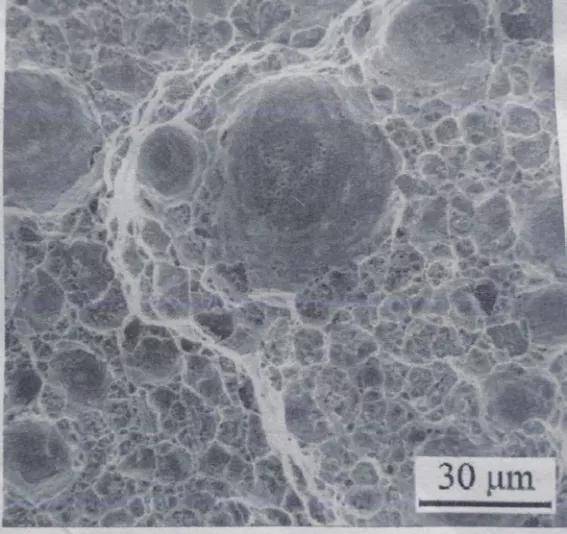
Fig. 2 Diagram of size dimples of CT643 fatigue fracture
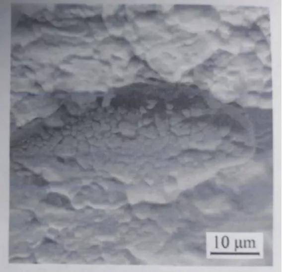
Fig. 3 Diagram of HL312 fatigue crack along grain fracture pattern
2.2 Micromechanism of crack propagation
The micro-mechanism of fatigue crack propagation is strongly affected by the slip characteristics, stress level and microstructure size of the filler metal. Ag-base solder is a ductile material, and fatigue crack propagation can be understood as that the plastic zone at the crack tip expands along the main slip direction in the way of pure shear. When the size of the plastic zone increases to larger than the grain size of the solder, zigzag crack propagation will occur. The zigzag crack of the fatigue crack is shown in Fig. 4.
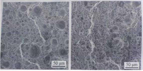
Fig. 4 Diagram of size dimples of CT643 fatigue fracture
3. Friction and wear mechanism of 65Mn steel and brazed diamond coating
Fig. 5 shows the friction and wear mechanism of 65Mn steel and brazed diamond coating. In the figure, V is the motion velocity of the sample, and P is the normal load of the sample. Based on the above studies on the friction and wear morphology and friction coefficient, combined with relevant literature, it is considered that the friction and wear mode between steel and ZrO 2 grinding ball is mainly adhesive wear. According to Archard's wear model calculation formula.
Q = KPL/H (1)
Where :Q is the total wear loss; K is the probability number of abrasive particles generated in the microconvex body; P is normal load; L is the sliding distance, which is controlled by the friction time and the friction speed. H is the hardness of the softer material.
In (1), the material wear is proportional to the sliding distance and the normal load, and inversely proportional to the hardness of the soft material.
The hardness of 65Mn steel is about 360HV, which is much smaller than that of ZrO 2, which is 15 -- HV -- 1800HV. As can be seen from Fig. 5a and Fig. 5b, when the 65Mn steel is rubbed with the ZrO 2 grinding ball, under the action of normal load, part of the microconvex between the two contact with each other, and then slide and form a short "run-in stage". The microconvex body of the 65Mn steel with low hardness is shearing so that the microconvex body of the steel with low hardness first breaks into abrasive debris. During this period, the friction increases the contact area and friction coefficient, but the wear velocity is low. Into a longer period of "stable wear" phase. At this stage, the wear rate changed little and the friction coefficient increased steadily. With the prolonging of friction time, the contact area between the two increases further, the wear debris of 65Mn steel increases, the adhesion wear intensifies, and the steel enters the "severe wear" stage.
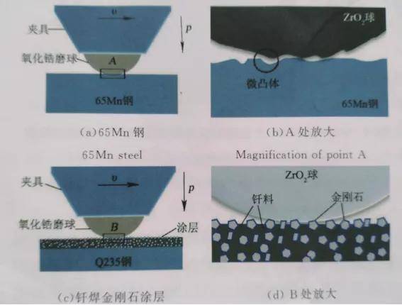
Fig. 5 Frictional and wear mechanism of coating 65Mn steel and brazed diamond
The friction and wear mode between brazed diamond coating and grinding ball is mainly two-body abrasive wear, and the wear mechanism is shown in Fig. 5C and Fig. 5D: Due to the chemical metallurgical bonding between the filler metal and diamond, the holding force of the filler metal on the diamond is relatively high. When grinding, the fixed abrasive particles of high hardness diamond raised in the coating slide relatively on the surface of ZrO 2 grinding ball. Under the normal load, the ZrO 2 grinding ball is ground and the abrasive chips are formed and scattered on the surface of the coating, while the ZrO 2 grinding ball forms the shape of furrow. With the ZrO 2 debris scattered on the surface of the coating, the "micro-rolling ball" effect gradually formed, which transformed part of sliding friction into rolling friction, and the friction coefficient showed a tendency to decrease. Therefore, the essence of the high abrasion resistance of brazed diamond coating is that the abrasion resistance of diamond with high hardness protruding in the coating is the main bearing phase in the friction, which makes the coating avoid wear to a certain extent, and thus protects the coating.
(1) the same applies to abrasive wear, the type of shape coefficient K can be interpreted as grits, size large, sharp, polygon grinding grain size smaller, dull, quick round of abrasive wear and tear, but grits' critical value at about 80 um, when particle size more than the critical value, wear is no longer increases with the increase of wear particle. In this experiment, the size of diamond abrasive particles used is basically above 80um, so the size of diamond particles does not affect the wear amount of ZrO2 grinding ball. , however, when the mass fraction of diamond phase in the coating at the same time, the diamond bit diameter, the greater the amount of the less, the convex surface of diamond is also less, thus grinding grain total sliding distance is smaller, according to the type (1) it is concluded that the less amount of ZrO2 grinding ball wear, in addition, due to the surface plating tungsten in the brazing diamond in a certain extent, to protect the diamond will not heat damage and destruction, kept their original sharpness, and under the same particle size of brazing diamond plating tungsten coating of ZrO2 grinding ball wear is higher than that of not plated diamond tungsten coating, and its friction coefficient is relatively high.